Category: CAN-BUS PROJECTS

CAN-ISO: Code configuration and test

08 Feb 20
admin
,
No Comments

In this section we will see how to configure the module RubinoLAB CAN-ISO on Arduino and how to test it.

To buy CAN-ISO: LINK

The implemented protocol uses a standard ASCII communication. This makes the system compatible with any program (Python, LabVIEW, MATLAB etc), simple to adapt to your project.

The first step is to install the MCP_CAN library (if you have not already installed it), in the Arduino editor. Here is the link of the library:

https://github.com/coryjfowler/MCP_CAN_lib

Create a project with the example code shown here or alternatively download the attached project and unpack it in your workbook.

CANINO_v2 CANINO_V2.zip

Compile and upload it to the Arduino module.

[pastacode lang=”cpp” manual=”%2F%2Frevisione%202%20del%2030%2F03%2F2018%2C%20con%20Arduino%201.8.5%0A%2F*%0A%20%20CAN%20BUS%20%2B%20ARDUINO%20–%3E%20CANINO%20interface%20%3A)%0A%20%20USB%20%3C–%3E%20CAN%20BUS%20interface%0A%20%20Author%3A%20Luigi%20Rubino%0A%0A%20%20Adesso%20accetta%203%20byte%20di%20indirizzo%0A%0A%20%20STRING%20EXAMPLE%3A%0A%20%20%4000A0102030405060708%5Cn%0A*%2F%0A%0A%23include%20%22mcp_can.h%22%0A%23include%20%3CSPI.h%3E%0A%0A%23define%20CAN0_INT%202%20%20%20%20%20%20%20%20%20%20%20%20%20%20%20%20%20%20%20%20%20%20%20%20%20%20%20%20%20%20%2F%2F%20Set%20INT%20to%20pin%202%0AMCP_CAN%20CAN0(10)%3B%20%20%20%20%20%20%20%20%20%20%20%20%20%20%20%20%20%20%20%20%20%20%20%20%20%20%20%20%20%20%20%2F%2F%20Set%20CS%20to%20pin%2010%0A%0A%0A%2F%2F%20the%20cs%20pin%20of%20the%20version%20after%20v1.1%20is%20default%20to%20D9%0A%2F%2F%20v0.9b%20and%20v1.0%20is%20default%20D10%0A%2F%2F%20Can_Bus_shield-ISO-v1%20is%20default%20D10%0A%2F%2Fconst%20int%20SPI_CS_PIN%20%3D%2010%3B%0A%2F%2FMCP_CAN%20CAN(SPI_CS_PIN)%3B%20%20%20%20%20%20%20%20%20%20%20%20%20%20%20%20%20%20%20%20%20%20%20%20%20%20%20%20%20%20%20%20%20%20%20%20%2F%2F%20Set%20CS%20pin%0A%0Aunsigned%20char%20buf%5B8%5D%3B%0Aunsigned%20char%20canId%3B%0Along%20unsigned%20int%20rxId%3B%0A%0A%0A%23define%20LEN_STRING%2010%0A%0Aunsigned%20char%20ReceivedString%5BLEN_STRING%5D%3B%20%20%2F%2Fstringa%20ricezione%20carattere%20da%20USB%0A%0Aint%20inByte%20%3D%200%3B%20%20%20%20%20%20%20%20%20%2F%2F%20incoming%20serial%20byte%0A%0A%2F%2Fglobal%20var%0Aint%20%20digValue%2C%20sign%3D1%3B%0Achar%20rxpos%2C%20rxpos2%3B%20%20%20%20%20%20%20%20%20%20%2F%2Fper%20il%20parser%20seriale%0Aint%20address%3B%20%20%20%20%20%20%20%20%20%20%20%20%20%20%20%20%2F%2Fcomando%20da%20eseguire%0Aint%20DT%3B%0A%0A%0Avoid%20setup()%20%7B%0A%20%20%2F%2F%20start%20serial%20port%20at%20115200%20bps%3A%0A%20%20Serial.begin(115200)%3B%20%2F%2Fprovare%20velocit%C3%A0%20115200%0A%20%20while%20(!Serial)%20%7B%0A%20%20%20%20%3B%20%2F%2F%20wait%20for%20serial%20port%20to%20connect.%20Needed%20for%20native%20USB%20port%20only%0A%20%20%7D%0A%20%0A%20%20%2F%2F%20Initialize%20MCP2515%20running%20at%2016MHz%20with%20a%20baudrate%20of%20500kb%2Fs%20and%20the%20masks%20and%20filters%20disabled.%0A%20%20if(CAN0.begin(MCP_ANY%2C%20CAN_500KBPS%2C%20MCP_16MHZ)%20%3D%3D%20CAN_OK)%0A%20%20%20%20Serial.println(%22MCP2515%20Initialized%20Successfully!%22)%3B%0A%20%20else%0A%20%20%20%20Serial.println(%22Error%20Initializing%20MCP2515…%22)%3B%0A%20%20%0A%20%20CAN0.setMode(MCP_NORMAL)%3B%20%20%20%20%20%20%20%20%20%20%20%20%20%20%20%20%20%20%20%20%20%2F%2F%20Set%20operation%20mode%20to%20normal%20so%20the%20MCP2515%20sends%20acks%20to%20received%20data.%0A%0A%20%20pinMode(CAN0_INT%2C%20INPUT)%3B%20%20%20%20%20%20%20%20%20%20%20%20%20%20%20%20%20%20%20%20%20%20%20%20%20%20%20%20%2F%2F%20Configuring%20pin%20for%20%2FINT%20input%0A%20%20%0A%20%20Serial.println(%22CANINO%20READY…%22)%3B%0A%7D%0A%0Avoid%20loop()%20%7B%0A%0A%20%20unsigned%20char%20len%20%3D%200%3B%0A%20%20%0A%20%20%2F%2F%20if%20we%20get%20a%20valid%20byte%2C%20read%20analog%20ins%3A%0A%20%20if%20(Serial.available()%20%3E%200)%20%7B%0A%20%20%20%20%2F%2F%20get%20incoming%20byte%3A%0A%20%20%20%20inByte%20%3D%20Serial.read()%3B%0A%20%20%20%20%2F%2FSerial.write(inByte)%3B%0A%20%20%20%20%2F%2F%20delay%2010ms%20to%20let%20the%20ADC%20recover%3A%0A%20%20%20%20%2F%2Fdelay(10)%3B%0A%20%20%20%20%0A%20%2F*%20Get%20the%20character%20received%20from%20the%20USART%20*%2F%0A%20%20if%20(inByte%3D%3D’%40′)%0A%20%20%20%7B%0A%20%20%20%20%20rxpos%20%20%20%20%20%3D%201%3B%0A%20%20%20%20%20digValue%20%20%3D%200%3B%0A%20%20%20%7D%0A%20%20else%0A%20%20%7B%0A%20%20%20%20%0A%2F%2F%20%20%20%20Serial.print(%22–%3E%22)%3B%0A%2F%2F%20%20%20%20Serial.print((int)%20rxpos)%3B%0A%2F%2F%20%20%20%20Serial.println()%3B%0A%20%20%20%20%0A%20%20switch(rxpos)%0A%20%20%7B%0A%20%20%20case%201%3A%0A%20%20%20%20%20%20address%20%20%20%3D%20hex2int(inByte)%3B%0A%20%20%20%20%20%20rxpos%20%20%20%20%2B%3D%201%3B%0A%20%20%20%20%20%20%0A%20%20%20%20%20%20break%3B%0A%0A%20%20%20case%202%3A%0A%20%20%20%20%20%20address%20%20%20%3C%3C%3D4%3B%20%0A%20%20%20%20%20%20address%20%2B%3D%20hex2int(inByte)%3B%20%20%20%20%20%0A%20%20%20%20%20%20rxpos%20%20%20%20%2B%3D%201%3B%0A%0A%20%20%20%20%20%20break%3B%0A%20%20%20%20%20%20%0A%20%20%20case%203%3A%0A%20%20%20%20%20%20address%20%20%20%3C%3C%3D4%3B%20%0A%20%20%20%20%20%20address%20%2B%3D%20hex2int(inByte)%3B%20%20%20%20%0A%20%20%20%20%20%20rxpos%20%20%20%20%2B%3D%201%3B%0A%20%20%20%20%20%20rxpos2%20%20%20%3D%20%200%3B%20%0A%0A%20%20%20%20%20%20break%3B%0A%20%20%20%20%20%20%20%20%20%20%20%20%20%20%20%20%20%20%0A%20%20%20case%204%3A%20%20%20%2F%2Fbyte%201%0A%20%20%20%20%20%20DT%20%3D%20hex2int(inByte)%3B%0A%20%20%20%20%20%20rxpos%20%20%20%20%2B%3D%201%3B%0A%20%20%20%20%20%20break%3B%0A%20%20%20case%205%3A%0A%20%20%20%20%20%20DT%20%20%20%3C%3C%3D4%3B%20%0A%20%20%20%20%20%20DT%20%2B%3D%20hex2int(inByte)%3B%0A%20%20%20%20%20%20ReceivedString%5Brxpos2%5D%20%3D%20DT%3B%0A%20%20%20%20%20%20rxpos%20%20%20%20%2B%3D%201%3B%0A%20%20%20%20%20%20rxpos2%20%20%20%2B%3D%201%3B%0A%20%20%20%20%20%20break%3B%0A%0A%20%20%20case%206%3A%20%20%20%2F%2Fbyte%202%0A%20%20%20%20%20%20DT%20%3D%20hex2int(inByte)%3B%0A%20%20%20%20%20%20rxpos%20%20%20%20%2B%3D%201%3B%0A%20%20%20%20%20%20break%3B%0A%20%20%20case%207%3A%0A%20%20%20%20%20%20DT%20%20%20%3C%3C%3D4%3B%20%0A%20%20%20%20%20%20DT%20%2B%3D%20hex2int(inByte)%3B%0A%20%20%20%20%20%20ReceivedString%5Brxpos2%5D%20%3D%20DT%3B%0A%20%20%20%20%20%20rxpos%20%20%20%20%2B%3D%201%3B%0A%20%20%20%20%20%20rxpos2%20%20%20%2B%3D%201%3B%0A%20%20%20%20%20%20break%3B%0A%20%0A%20%20%20case%208%3A%20%20%20%2F%2Fbyte%203%0A%20%20%20%20%20%20DT%20%3D%20hex2int(inByte)%3B%0A%20%20%20%20%20%20rxpos%20%20%20%20%2B%3D%201%3B%0A%20%20%20%20%20%20break%3B%0A%20%20%20case%209%3A%0A%20%20%20%20%20%20DT%20%20%20%3C%3C%3D4%3B%20%0A%20%20%20%20%20%20DT%20%2B%3D%20hex2int(inByte)%3B%0A%20%20%20%20%20%20ReceivedString%5Brxpos2%5D%20%3D%20DT%3B%0A%20%20%20%20%20%20rxpos%20%20%20%20%2B%3D%201%3B%0A%20%20%20%20%20%20rxpos2%20%20%20%2B%3D%201%3B%0A%20%20%20%20%20%20break%3B%0A%0A%20%20%20case%2010%3A%20%20%20%2F%2Fbyte%204%0A%20%20%20%20%20%20DT%20%3D%20hex2int(inByte)%3B%0A%20%20%20%20%20%20rxpos%20%20%20%20%2B%3D%201%3B%0A%20%20%20%20%20%20break%3B%0A%20%20%20case%2011%3A%0A%20%20%20%20%20%20DT%20%20%20%3C%3C%3D4%3B%20%0A%20%20%20%20%20%20DT%20%2B%3D%20hex2int(inByte)%3B%0A%20%20%20%20%20%20ReceivedString%5Brxpos2%5D%20%3D%20DT%3B%0A%20%20%20%20%20%20rxpos%20%20%20%20%2B%3D%201%3B%0A%20%20%20%20%20%20rxpos2%20%20%20%2B%3D%201%3B%0A%20%20%20%20%20%20break%3B%0A%20%20%20%20%20%20%0A%20%20%20case%2012%3A%20%20%20%2F%2Fbyte%205%0A%20%20%20%20%20%20DT%20%3D%20hex2int(inByte)%3B%0A%20%20%20%20%20%20rxpos%20%20%20%20%2B%3D%201%3B%0A%20%20%20%20%20%20break%3B%0A%20%20%20case%2013%3A%0A%20%20%20%20%20%20DT%20%20%20%3C%3C%3D4%3B%20%0A%20%20%20%20%20%20DT%20%2B%3D%20hex2int(inByte)%3B%0A%20%20%20%20%20%20ReceivedString%5Brxpos2%5D%20%3D%20DT%3B%0A%20%20%20%20%20%20rxpos%20%20%20%20%2B%3D%201%3B%0A%20%20%20%20%20%20rxpos2%20%20%20%2B%3D%201%3B%0A%20%20%20%20%20%20break%3B%0A%0A%20%20%20case%2014%3A%20%20%20%2F%2Fbyte%206%0A%20%20%20%20%20%20DT%20%3D%20hex2int(inByte)%3B%0A%20%20%20%20%20%20rxpos%20%20%20%20%2B%3D%201%3B%0A%20%20%20%20%20%20break%3B%0A%20%20%20case%2015%3A%0A%20%20%20%20%20%20DT%20%20%20%3C%3C%3D4%3B%20%0A%20%20%20%20%20%20DT%20%2B%3D%20hex2int(inByte)%3B%0A%20%20%20%20%20%20ReceivedString%5Brxpos2%5D%20%3D%20DT%3B%0A%20%20%20%20%20%20rxpos%20%20%20%20%2B%3D%201%3B%0A%20%20%20%20%20%20rxpos2%20%20%20%2B%3D%201%3B%0A%20%20%20%20%20%20break%3B%0A%0A%20%20%20case%2016%3A%20%20%20%2F%2Fbyte%207%0A%20%20%20%20%20%20DT%20%3D%20hex2int(inByte)%3B%0A%20%20%20%20%20%20rxpos%20%20%20%20%2B%3D%201%3B%0A%20%20%20%20%20%20break%3B%0A%20%20%20case%2017%3A%0A%20%20%20%20%20%20DT%20%20%20%3C%3C%3D4%3B%20%0A%20%20%20%20%20%20DT%20%2B%3D%20hex2int(inByte)%3B%0A%20%20%20%20%20%20ReceivedString%5Brxpos2%5D%20%3D%20DT%3B%0A%20%20%20%20%20%20rxpos%20%20%20%20%2B%3D%201%3B%0A%20%20%20%20%20%20rxpos2%20%20%20%2B%3D%201%3B%0A%20%20%20%20%20%20break%3B%0A%0A%20%20%20case%2018%3A%20%20%20%2F%2Fbyte%208%0A%20%20%20%20%20%20DT%20%3D%20hex2int(inByte)%3B%0A%20%20%20%20%20%20rxpos%20%20%20%20%2B%3D%201%3B%0A%20%20%20%20%20%20break%3B%0A%20%20%20case%2019%3A%0A%20%20%20%20%20%20DT%20%20%20%3C%3C%3D4%3B%20%0A%20%20%20%20%20%20DT%20%2B%3D%20hex2int(inByte)%3B%0A%20%20%20%20%20%20ReceivedString%5Brxpos2%5D%20%3D%20DT%3B%0A%20%20%20%20%20%20rxpos%20%20%20%20%2B%3D%201%3B%0A%20%20%20%20%20%20rxpos2%20%20%20%2B%3D%201%3B%0A%20%20%20%20%20%20break%3B%0A%20%20%20%20%20%20%20%20%20%20%20%20%20%20%20%20%20%20%0A%20%20%20case%2020%3A%20%2F%2Feseguo%20il%20comando%0A%20%20%20%20%20%20%20%20CAN0.sendMsgBuf(address%2C%200%2C%208%2C%20ReceivedString)%3B%0A%20%20%20%20%20%20%20%20%2F%2Fbyte%20sndStat%20%3D%20CAN0.sendMsgBuf(0x100%2C%200%2C%208%2C%20data)%3B%0A%20%20%20%20%2F%2Fdelay(100)%3B%20%20%20%20%20%20%20%20%20%20%2F%2F%20send%20data%20per%20100ms%0A%20%20%20%20%20%20rxpos%20%20%20%20%3D%200%3B%0A%0A%2F%2Fda%20rinuovere%0A%2F%2F%20%20%20%20%20%20Serial.print(address%2C%20HEX)%3B%0A%2F%2F%20%20%20%20%20%20for%20(int%20kk%3D0%3Bkk%3C%3D7%3B%20kk%2B%2B)%0A%2F%2F%20%20%20%20%20%20%7B%0A%2F%2F%20%20%20%20%20%20%20%20Serial.print(%22%20%22)%3B%0A%2F%2F%20%20%20%20%20%20%20%20Serial.print(ReceivedString%5Bkk%5D%2C%20HEX)%3B%0A%2F%2F%20%20%20%20%20%20%20%20%0A%2F%2F%20%20%20%20%20%20%20%20%7D%0A%2F%2F%20%20%20%20%20%20%20%20Serial.println()%3B%0A%20%20%20%20break%3B%0A%20%20%20%20default%3A%20%0A%20%20%20%20%20%20%20%20rxpos%20%20%20%20%3D%200%3B%0A%20%20%20%20%20%20%20%20break%3B%0A%20%20%7D%0A%20%20%7D%20%20%20%20%2F%2Ffine%20gestione%20acquisizione%20%0A%20%20%7D%20%20%2F%2Ffine%20gestione%20seriale%0A%0A%20%20%2F%2F%20————————————————–%0A%20%20%2F%2Fgestione%20CAN%20BUS%0A%20%20if(!digitalRead(CAN0_INT))%20%20%20%20%20%20%20%20%20%20%20%20%20%20%20%20%20%20%20%20%20%20%20%20%20%2F%2F%20If%20CAN0_INT%20pin%20is%20low%2C%20read%20receive%20buffer%0A%20%20%7B%0A%20%20%20%20CAN0.readMsgBuf(%26rxId%2C%20%26len%2C%20buf)%3B%20%20%20%20%20%20%2F%2F%20Read%20data%3A%20len%20%3D%20data%20length%2C%20buf%20%3D%20data%20byte(s)%0A%0A%20%20%20%20canId%20%3D%20(unsigned%20char)%20rxId%3B%0A%2F%2F%20%20%20%20canId%20%3D%20CAN0.getCanId()%3B%20%20%20%20%20%20%20%2F%2F%20indirizzo%20risposta%0A%20%20%20%20%20%20%20%20%0A%20%2F%2F%20%20%20%20%20%20%20Serial.println(%22—————————–%22)%3B%0A%20%2F%2F%20%20%20%20%20%20%20Serial.print(%22Get%20data%20from%20ID%3A%20%22)%3B%0A%20%20%20%20%20%20%20%20Serial.print(%22%40%22)%3B%0A%20%20%20%20%20%20%20%20Serial.print(canId%2C%20HEX)%3B%0A%0A%20%20%20%20%20%20%20%20for(int%20i%20%3D%200%3B%20i%3Clen%3B%20i%2B%2B)%20%20%20%20%2F%2F%20print%20the%20data%0A%20%20%20%20%20%20%20%20%7B%0A%20%20%20%20%20%20%20%20%20%20%20%20if%20(buf%5Bi%5D%3C%3D15)%20%20%7B%20%20Serial.print(‘0’)%3B%7D%0A%20%20%20%20%20%20%20%20%20%20%20%20Serial.print(buf%5Bi%5D%2C%20HEX)%3B%0A%20%20%20%20%20%20%20%20%7D%0A%20%20%20%20%20%20%20%20Serial.println()%3B%0A%20%20%20%20%7D%0A%20%0A%7D%0A%0Avoid%20establishContact()%20%7B%0A%20%20while%20(Serial.available()%20%3C%3D%200)%20%7B%0A%20%20%20%20Serial.print(‘A’)%3B%20%20%20%2F%2F%20send%20a%20capital%20A%0A%20%20%20%20delay(300)%3B%0A%20%20%7D%0A%7D%0A%0Aint%20hex2int%20(char%20c)%0A%7B%0A%20%20if%20(c%20%3E%3D%20’0’%20%26%26%20c%20%3C%3D%20’9′)%0A%20%20%7B%0A%20%20%20%20%20%20return%20(int)%20(c-‘0′)%3B%0A%20%20%7D%0A%20%20else%0A%20%20%7B%0A%20%20%20%20%20%20return%20(int)%20((c%20-%20’A’)%2B10)%3B%0A%20%20%7D%0A%7D%0A” message=”CANINO library” highlight=”” provider=”manual”/]

Now we are ready to start!

Code test (Transmission)

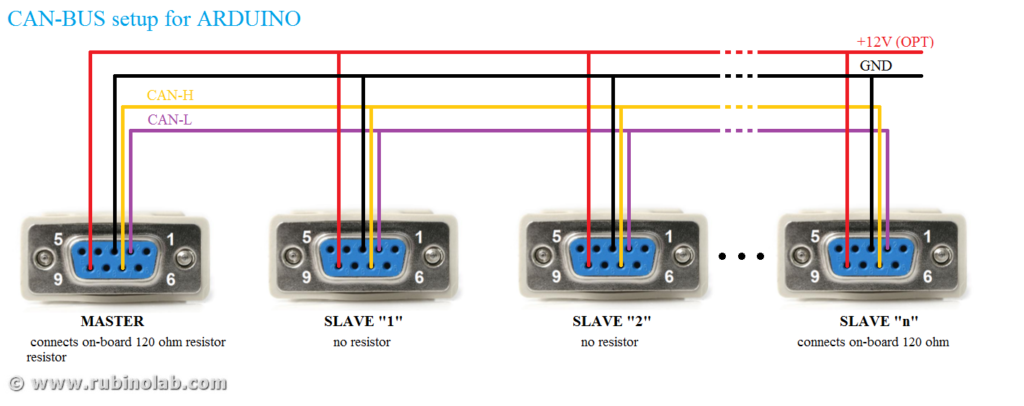
A typical CAN-Bus connection in the industrial automation domain is shown in the figure, where there is a master and several multi slaves. In the master/slave one device or process (known as the master) controls one or more other devices or processes (known as slaves). Once the master/slave relationship is established, the direction of control is always from the master to the slave(s).
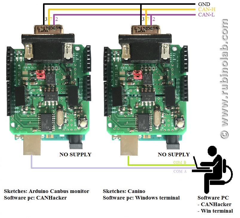
For the code test it is necessary to create a CAN-BUS micro-network, for example using two Arduino CAN-BUS interfaces.

For the example code shown here we used an Arduino CAN-BUS interface connected to a commercial CAN-BUS interface.

NB. The interface is configured for a CAN communication speed of 500kbps. Change this value in the code for a different speed. The addresses are configured to 11bit.

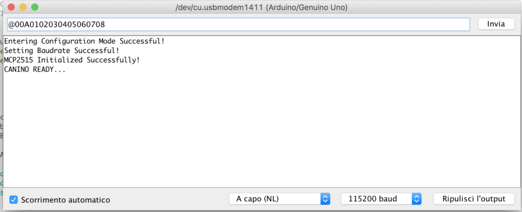
Open the serial terminal from the Arduino editor and configure it for a speed of 115200 baud, no flow control.

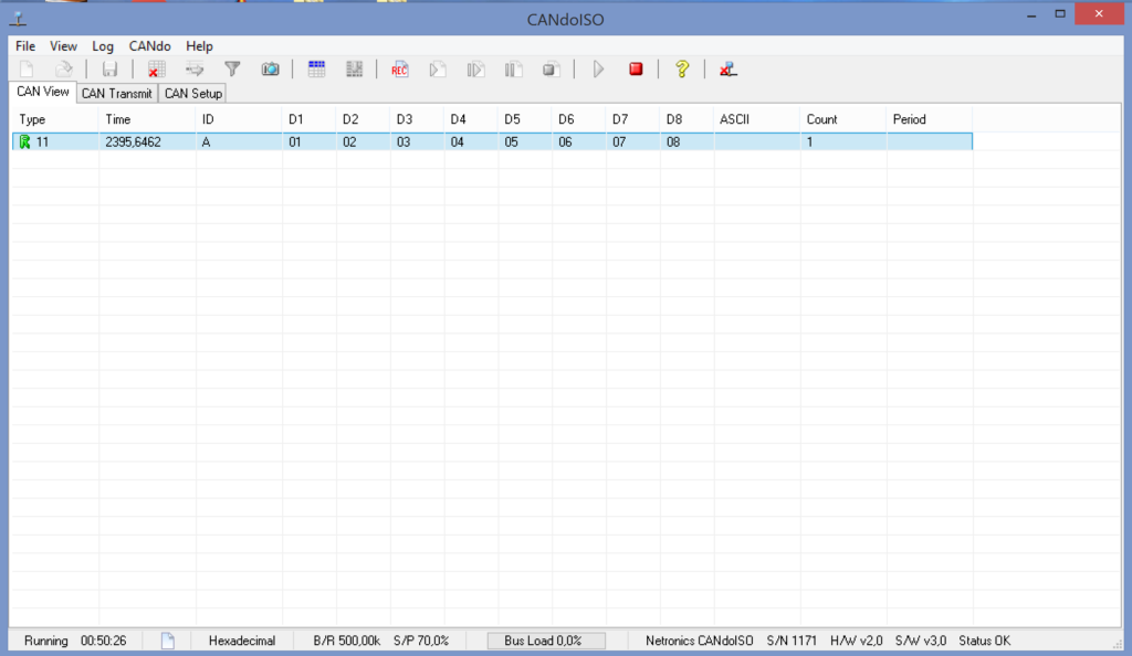
Enter the following string: @00A0102030405060708 and press enter.

The string consists of three parts:

  • @ (Attention) warns the interface that a new string is coming and that it must realign for a new send
  • 00A destination address
  • 01 02 03 04 05 06 07 08 are the 8 bytes to be sent in hexadecimal format. Recall that a hexadecimal byte is between 00 and FF.
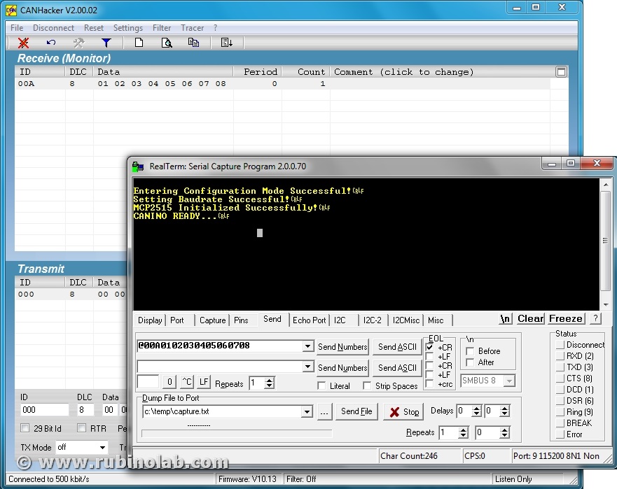
If all the operations have been carried out correctly, the other interface will receive at the address 0A the bytes as in the sequence shown.
Code test (Reception)

For the reception code test, the reverse operation is performed.

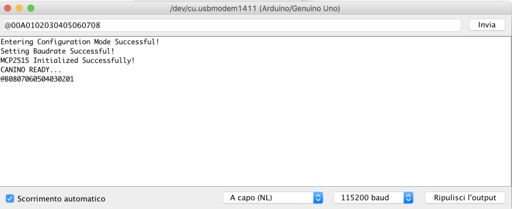
We send to the address 0B, the string 08 07 06 05 04 03 02 01

In reception we will have an ASCII string formatted in the same way as the transmission, as shown below:
Example (Canino+LabView)

A YouTube video where CAN-ISO communicates with a CAN BUS industrial device, using the “CANINO” code and the “LabView” graphical interface:

Conclusions

Now that the code is tested and we are able to transmit / receive a generic package, appropriately formatted, the next step is to use the interface with a program. In the next tutorial we will see how to use the interface with Python, LabVIEW, MATLAB, bash shell and others.

Contact us to let us know your opinionsinfo(at)rubinolab dot com

To buy CAN-ISO: LINK

Enjoy!

Comparison isolated galvanically converter USB – CAN BUS

08 Jan 20
admin
,
No Comments

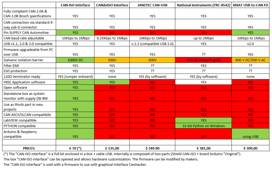
This article reports a comparison between CAN-ISO (of RubinoLAB) with commercial USB-CAN BUS product (galvanically isolated).
Since there are no “galvanically isolated” CAN bus shields on the market for Arduino or similar platforms, the RubinoLab Team has compared CAN-ISO with the best interfaces on the market that allow to use both proprietary and new interfaces for customization.

Comparing the data shows that the CAN-ISO interface (RubinoLAB) is the only solution with “open software”, all others have limitations on the use platforms (typically OS Windows), firmware, and use of proprietary software.
This allows use in the industrial, and low-cost automotive sector.
CAN-ISO has two power inputs (but only one power supply): USB and pin on CAN connector. Typically via USB for use as a sniffer connected to the PC, from pins on CAN connector to create a stand-alone device with remote power supply (not connected to the PC). The two power supplies guarantee galvanic isolation and power supply of the CAN-ISO shield and the Arduino board (or compatible).
CAN-ISO has many free pins on the shield and allows you to connect displays, buttons, potentiometers, sensors, etc. to create new devices with bi-insulated CAN-BUS bidirectional connectivity.
Excellent for creating a CAN test bench for control units with interfaces created ad hoc.

Contact us to let us know your opinionsinfo(at)rubinolab dot com

To buy the CAN-ISO: LINK

Enjoy!

Clone Arduino & driver chip CH340, CH340G, CH341

08 Jul 19
admin
,
No Comments

The CH340/CH341 chip is used by a number of Arduino compatible cards to provide USB connectivity.
Many operating systems do not recognize these chip natively because they lack the drivers and consequently we have an error due to lack of drivers.
The lack of this driver does not allow you to communicate with the hardware platforms and to use the Arduino development software.

No panic, driver installation is very easy!

The driver must be downloaded from the official (Chinese) website.

Once the unzip of the package has been executed, it is possible to proceed with the update of the driver for the device CH340/CH341 and equivalent (download driver only for your OS):


WINDOWS 32/64bit (version: 3.4 – 2016/09/27)

Drivers in the Windows OS are missing, you need to download and install them.

(WINDOWS 32/64bit) for Windows 10/8.1/8/7/VISTA/XP/2000/ME/98 & SERVER 2016/2012/2008/2003


LINUX 32/64bit (version: 1.5 – 2018/03/18)

The drivers are integrated into different Linux distributions. If the device is not recognized, download the Linux CH340/CH341 driver.

(LINUX 32/64bit)


MAC OS 32/64bit (version: 1.5 – 2018/07/05)

This driver is for MacOS Sierra/High Sierra. Do not install the drivers for the Mojave, because it seems that the latest versions are equipped with the built CH340/CH341 support.

(MAC OS 32/64bit) for MacOS Sierra/High Sierra

Installation
• Unplug any CH34* devices.
• Unload the old drivers if running:
• sudo kext unload /Library/Extensions/usbserial.kext
• sudo kext unload /System/Library/Extensions/usb.kext
• Remove the old driver by issuing one of the following commands (depending on your installation):
• sudo rm -rf /System/Library/Extensions/usb.kext
• sudo rm -rf /Library/Extensions/usbserial.kext
• Double-click on the CH34x_Install_V1.3.pkg file and install (no need to reboot)
• Instead of rebooting, you can force quit Installer after it completes.
• Load the new driver:
• sudo kextload /Library/Extensions/usbserial.kext
• Plug in your device. It should now be listed under the /dev directory. Examples:
• /dev/cu.wchusbserial1410
• /dev/cu.wchusbserial1420


ANDROID (version: 1.5 – 2018/03/18)

Android 3.1 – USB Host, root, apk, lib, (Java Driver), App Demo, (USB UART Demo SDK)


Enjoy!

EOBD socket (European On Board Diagnostic)

07 Dec 18
admin
, ,
No Comments

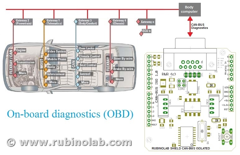
With the term OBD or OBD-II, in the automotive, motorcycle or motoring context in general, it is a generic term that refers to the ability of self-diagnosis and error reporting of a vehicle. Technically his name is J1962 and in Europe he is called by the term EOBD.

The communication protocol used for the OBD (On Board Diagnostics) is the CAN (Controller Area Network) that can communicate with the “Body computer” to which all the devices of a vehicle are connected.

It is essential to distinguish the roles of the two CAN and OBD-II protocols.

The CAN (controller area network) protocol is a serial digital communication bus of the “broadcast” type: it allows distributed real-time control with a very high level of security. It was introduced by Bosch in the early 1980s for automotive applications, to enable communication between intelligent electronic devices mounted on a vehicle, but has now spread to many sectors of the industry. But in order for there to be communication between the CAN devices, the data received must be uniquely identified and consequently the OBD was introduced. The OBD-II protocol, much more detailed than the CAN, was born expressly as a standard for transport vehicles and has become mandatory in America in vehicles produced since 1996. The European version of this standard is called EOBD, it is substantially identical to OBD-II and is mandatory since 2001.

The OBD-II not only defines the communication standard, but also the connector that must be present in the vehicle interior for the connection of compatible OBD-II instruments. This connector is substantially a connection port to the CAN bus (or other bus present on the vehicle). When this connector is connected to an instrument with an OBD-II interface, it is practically connected to the CAN bus and is able to do two things:

  • “Reading” passively. All the messages sent by the control units on the bus and transmit them to the user’s computer (or other device).
  • “Writing” actively with the control units, requesting data and then transmitting the replies received to the computer (or other device).

Like all active systems, it is possible to send commands to modify the operating parameters, so it is advisable to limit yourself to sending the messages you know the effect of, because different messages could alter the functioning of the car and this can be dangerous.

The OBD-II connector also includes a line that supplies power to the connected device. It is important to know that the connector in many vehicles always supplies energy, even when it is switched off and a diagnostic tool always connected to the vehicle (even with the engine off) could cause the battery to discharge since it always keeps the control units that are not in the Energy Saver active. For these reasons it is recommended to disconnect the diagnostic connector after each use to preserve the vehicle battery charge.

OBD-II

The OBD-II standard also defines some commands for controlling the output, the self-monitoring modes and for clearing the KAM memory (Keep Alive Memory).

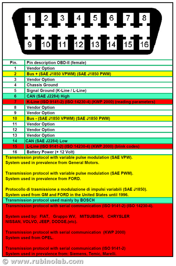
The OBD-II connector is identical for all models but there are five different communication protocols:

  • VPW (Variable pulse width): General Motors
  • PWM (Pulse-width modulation): Ford
  • ISO 9141: Chrysler in Asia and Europa
  • ISO 14230 KWP2000 (Keyword Protocol 2000 on line K)
  • ISO 15765 (via CAN line, as SAE-J2284)

It also provides information on all relevant parameters and errors for the purposes of polluting emissions:

  • Parameter codes (RLI)
  • Speed
  • Rpm
  • Error codes (DTC)
  • Oxygen sensor

The reading of the error components is standardized, so any workshop even without the official tool of the house, must be able to read the OBD errors.

Notes: For petrol engines before 2001, instead of OBD-II we talk about OBD-I, ie an on-board diagnosis related to electrical errors only.

The EOBD regulation European On Board Diagnostics (European On Board Diagnostics) is the European equivalent of OBD-II and was introduced for petrol engines in 2001 together with the Euro 3 emission level with Directive 98/69/CE[1].

The EOBD applies to all M1 class vehicles (with no more than 8 seats and a gross vehicle weight of up to 2500 kg) registered for the first time within the EU Member States from 1 January 2001 for petrol-powered cars and from 1 January 2004 for cars with diesel engines. For the newly introduced models, the dates of application of the legislation were brought forward by one year: 1 January 2000 for petrol-driven cars and 1 January 2003 for diesel-powered cars.

For cars with a gross vehicle weight greater than 2500 kg and for light commercial vehicles, the dates of application of the legislation started from 1 January 2002 for petrol models, and from 1 January 2007 for diesel models.

Note: If the pin 15 contact is present in the EOBD2 socket, the procedure for reading the error codes can be performed. Connect the pin 15 (if present) with the ground pin 5 and the diagnostic indicator and the error code list identify the error code in memory.

On some cars the flash code is available on pin 13.

EOBD-II – Fault Codes

EOBD fault codes European On Board Diagnostics are composed of five characters: a letter, followed by four numbers.

The letter refers to the system that is referenced (eg Pxxxx refers to the propulsion system) while if the next character is a 0 indicates compliance with the EOBD European On Board Diagnostics standard, if it is a different number it falls within the manufacturer’s proprietary code table and may vary depending on the system diagnosed. The third character refers to a subsystem, eg:

  • P00xx – Fuel measurement and air intake, auxiliary emission control
  • P01xx – Fuel measurement and air intake
  • P02xx – Fuel measurement and air intake (injection system)
  • P03xx – Injection control and missed ignitions
  • P04xx – Auxiliary emission control
  • P05xx – Vehicle speed control and engine minimum adjustment system
  • P06xx – Control unit communication system control
  • P07xx – Transmission system control
  • P08xx – Transmission system control

For the complete table of codes: OBD II Standard Fault Codes

Now let’s take the CAN-BUS ISO and we prepare the connection cable for reading the values on EOBD!

Enjoy!

CAN-ISO with CANHacker graphic interface

05 Nov 18
admin
,
No Comments

In this section we will see how to make an “Universal isolated galvanic CAN BUS monitor” using Arduino with a CAN-ISO shield (RubinoLab) and a graphic interface CANHacker.

A complete professional device for all CAN-BUS protocols, from the automotive to the industrial sector.

To buy CAN-ISO: LINK

A CAN network device that allows to write / read on CAN-bus to perform operations such as diagnostics, analyze network traffic, identify network problems, etc. For example:

In the automotive sector: it can be used to read the error codes of the cars, motorcycles, etc. that use OBD-II, or carry out operations of “CAN Bus Reverse Engineering” by monitoring the exchange of CAN data between engine side units, or send commands to reset error codes, perform bench tests of individual subsystems, etc

In the industry: with network monitoring you can help managers of a CAN network to identify whether a network is working normally or is congested. In addition, bottlenecks can be identified within a network to identify and improve performance with upgrades to the infrastructure.

Identification of problems: As mentioned above, in addition to reading / writing to CAN you can identify all the problems related to the network. By reading the information acquired by the sniffer it is possible to identify the wrong packets and / or identify the node that has not responded to the requests. This facilitates the identification of defective devices within the network efficiently and provides the ability to take quick corrective actions.

Here’s what you need

Buy the hardware:

Download the software:

Now we are ready to start!

Features

Before installation, let’s see what they are and what they do “Arduino canbus monitor” and “CANHacker tool”.

The sketch “Arduino canbus monitor”, implements CAN ASCII/SLCAN protocol compatible with Lawicel CAN232/CANUSB. It can be used for monitoring a large part of CAN protocols. Note: For CAN speeds exceeding 500kbps with a high data density on the serial port of Arduino, the serial port can become a bottleneck.

The graphic interface windows “CANHacker tool” of (Lawicel) can be interfaced to “Arduino canbus monitor”. It implements communication CAN with:

  • send & receive Can Frames
  • supports standard (11 bit) & extended (29 bit) frames
  • supports remote frames (RTR)
  • supports filter by ID (mask + code)
  • supported can baudrates from 10Kbps up to 1Mbps
  • support MCP2515 @ 16 MHZ

Now we will see step by step how to install the software “Arduino canbus monitor”  and “CANHacker tool”.

Installation

After downloading “Arduino canbus monitor”:

  1. load sketch “arduino-canbus-monitor.ino”
  2. Compile and if there are no errors continue to step 3. If there are errors about missing libraries (“mcp_can.h” and “can-232.h”) zip the files into a folder (can-232.cpp, can-232.h, mcp_can.cpp, mcp_can.h, mcp_can_dfs.h) and then from the Arduino IDE: Sketch -> Include Library -> Add .ZIP Library. Restart the Arduino IDE and go to point 1.
  3. Load to Arduino platform
  4. Disconnect and reconnect Arduino to USB

Now download “CANHackerV2.00.02.exe” and install the software to Windows platform.  After installation, restart Windows. Now it’s ready.

Usage

Now we can start using ours “sniffer” or “monitor canbus”.

  1. Connect the CAN Device (Arduino+CAN-ISO shield) to PC. Wait for Windows assign a COM serial port number. Check the serial port number assigned by windows in “device management”.
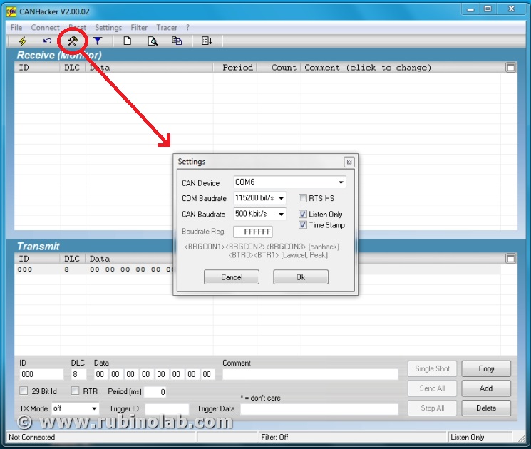
  2. Start the software CANHacker, and in “Setting” choose:
  • CAN Device: the COM port assigned to Arduino from windows
  • COM Baudrate: 115200 bits/s
  • CAN Baudrate: CAN port speed

Click on the button “OK”, then “Connect”. Have fun! Monitor your Can bus, save traces, send messages, do what your analyzer/visualizer software can.

EXAMPLE 01

In this test we will carry out Canbus communication tests between two “Arduino UNO” boards with “CAN-ISO” shields.

For the test we need:

(2) boards “ARDUINO UNO”
(2) Shields “CAN-ISO”
(1) cable Canbus

In order to use the same PC to read/write on the Canbus, we will use a “Windows terminal” and “CANHacker” as graphic interfaces.

As result, the download sketches on the first Arduino board is “CANINO”, in the second “Arduino canbus monitor”
Download CANINO
Download Arduino canbus monitor

Now launch the terminal:
CANHacker: configure the COM port, CAN speed (for board with Arduino canbus monitor);
CANINO: configure the COM port, CAN speed (for board with Canino);

In the figure, for example, we can see the sending of the string @00A0102030405060708 from “Windows terminal” of CAN to “CANHacker”.

Conclusions

With this solution we will have a complete tool, galvanically isolated for multiple uses, at low cost.

Contact us to let us know your opinionsinfo(at)rubinolab dot com

To buy CAN-ISO: LINK

Enjoy!